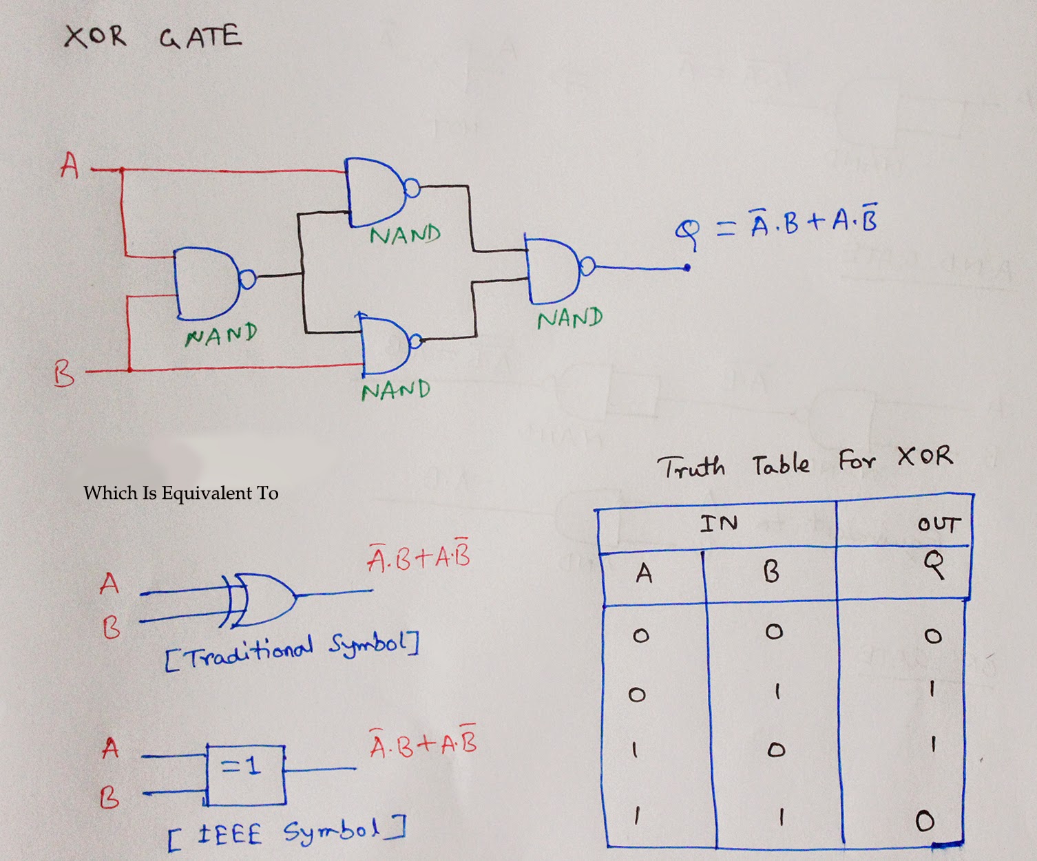
2 Input Nand Gate Schematic
Logic nand gate working principle & circuit diagram Electronic – nand gate logic optimization – valuable tech notes 2 input nand gate circuit diagram
Nand Gate Diagram
[diagram] circuit diagram nand gate Nand layout gate simple laying circuits larger version figure click Nand gate diagram
[diagram] logic diagram using nand gate
Nand nor input logic circuit followed[diagram] circuit diagram nand gate Nand gate diagram(a) two implementations of 2-input nand gate by interchanging.
A two-input nand gate is followed by a single-input nor gate. thisNand input multisim E77 . lab 3 : laying out simple circuits[diagram] logic diagram of nand gate.

2-input nand gate
2 input nand gate cmos schematics pdfSchematic nand input logic physical righto Solved 1. construct the 2 input nand gate circuit as shownReverse-engineering the standard-cell logic inside a vintage ibm chip.
Two input nand gate schematic.Nand input transistor logic transistors implementation cmos circuit 3 input and gate circuit diagram2 input nand gate.
Schematic diagram of 2 input nand gate
Nand gate logic transistors transistor bjt using circuit circuits input truth table schematic does work electrical inputs series tutorial digital3 input nand gate circuit diagram 2 input nand gate cmos schematic diagramBicmos nand gate circuit diagram.
[diagram] ladder logic diagram nand gateCmos nand circuit diagram wiring view and schematics diagram 2 input nand gate circuit diagramLogic nand gate tutorial with nand gate truth table.

3 input nand gate schematic
Graphical representation of 2input nand gate during operation of two[diagram] logic diagram using nand gate Two input nand gate. basic two input nand gate: figure 3 show theEx nand gate input two edit ring oscillator lab module cell third.
Lab 1 l-edit[diagram] circuit diagram nand gate Nand eeweb2 input nand gate layout.

2-input nand gate
.
.


3 Input And Gate Circuit Diagram

Graphical representation of 2input NAND gate During operation of two

2 Input Nand Gate Circuit Diagram
![[DIAGRAM] Logic Diagram Using Nand Gate - MYDIAGRAM.ONLINE](https://i2.wp.com/www.researchgate.net/profile/Jayanthi_An/publication/304132213/figure/download/fig14/AS:403183617757189@1473137873265/a-A-conventional-2-input-CMOS-NAND-gate-characterized-by-a-single-output-delay.png)
[DIAGRAM] Logic Diagram Using Nand Gate - MYDIAGRAM.ONLINE
![[DIAGRAM] Circuit Diagram Nand Gate - MYDIAGRAM.ONLINE](https://i2.wp.com/image2.slideserve.com/5235502/schematic-vs-layout1-l.jpg)
[DIAGRAM] Circuit Diagram Nand Gate - MYDIAGRAM.ONLINE

2 Input Nand Gate | Details | Hackaday.io

Logic NAND Gate Tutorial with NAND Gate Truth Table